
Valve Symbols for P&ID: Butterfly, Check, Gate, and Ball Valve Symbols
What is P&ID?
A Piping and Instrumentation Diagram (P&ID) is a key engineering drawing used to describe industrial process systems. It plays a crucial role in design, construction, operation, and maintenance by providing a standardized visual representation of piping, instruments, valves, and control systems.
Recognizing P&ID symbols is essential for interpreting system components and connections. This knowledge helps in identifying issues, troubleshooting failures, and ensuring smooth operation of industrial processes.
Key Information in a P&ID
-
Equipment ; Piping Information
Major equipment (e.g., pumps, heat exchangers, reactors)
Secondary equipment (e.g., filters, condensers)
Piping details (pipe numbering, diameter, material, pressure rating) -
Insulation and heating requirements
Instrumentation ; Control Systems
Process control loops (e.g., PID controllers, flow meters, pressure sensors)
Instrument tags (e.g., FT = Flow Transmitter, PT = Pressure Transmitter)
Control systems (e.g., DCS = Distributed Control System, PLC = Programmable Logic Controller) -
Valve Information
Various control valves (e.g., butterfly valves, gate valves, ball valves, check valves, safety valves)
Safety ; interlock features (e.g., emergency shut-off, overpressure protection)
The Role of P&ID
P&ID (Piping and Instrumentation Diagram) serves as a critical document in various stages of a project:
- Primary reference for construction, installation, and commissioning.
- Guides the design and programming of process control systems.
- Used by maintenance and operational staff for troubleshooting and daily operations.
- Provides a basis for safety analysis and HAZOP (Hazard and Operability Study).
Valve Symbols: The "Key Characters" in P&ID
Valves are the core components controlling fluid flow, and the accuracy of their symbols directly impacts the reliability of system design. Below are common P&ID valve symbols:
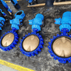
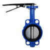
Butterfly Valve Symbol: A circle with a straight or diagonal line through the center (resembling butterfly wings). The diagonal line indicates the valve disc's opening angle.
Function: Quickly regulates flow by rotating the disc, ideal for large-diameter, low-pressure applications (e.g., ventilation, water supply).
Gate Valve Symbol: Two opposing hollow triangles with a vertical line in between (representing the gate's movement).
Function: Used to fully shut off or open flow, not suitable for frequent flow regulation.
Ball Valve Symbol: Two opposing hollow triangles with a circle in between (representing the ball).
Function: Achieves full open/close by rotating the ball, offering excellent sealing and suitable for quick shut-off.
Globe Valve Symbol: Similar to the ball valve symbol, but with a solid black circle in the center.
Function: Provides precise flow regulation but results in higher pressure drop.
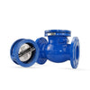
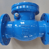
Check Valve Symbol: An arrow on a horizontal pipeline, pointing in the allowed flow direction.
Function: Prevents backflow by automatically closing when fluid flows in the reverse direction.

While the previously mentioned valves are primarily used for flow control (on/off or throttling) in 2-way inline configurations, multi-port valves (such as 3-way and 4-way valves) follow a similar symbolic structure. Each port or "passage" is represented by a triangle, indicating the flow paths and connections

End Connection Symbols
End connections are depicted using specific symbols to represent how the valve is connected to the piping system:
- Flanged Connection: Represented by a vertical line at the end of the pipe, parallel to the side of the valve symbol, with a small gap in between. This indicates that the valve can be removed without cutting the pipeline.
- Threaded Connection: Shown as a small hollow circle at the connection point.
- Welded Connection: Represented by a small solid square at the connection point.
- Socket Weld Connection: Shown as a small hollow or unfilled square at the connection point.
Below is an example of a butterfly valve connection symbol:

Valve Actuator Symbols
In Piping and Instrumentation Diagrams (P&ID), actuator symbols are used in conjunction with the type of valve they control (e.g., ball valve, butterfly valve) and are labeled to indicate the method of operation (pneumatic, electric, hydraulic, etc.). Below are the standard actuator symbols and their detailed explanations.
Common Actuator Types and Symbols:
- Pneumatic Actuator: Represented by a semicircle or circle next to the valve symbol, with the letter "P" (Pneumatic) inside.
- Electric Actuator: Indicated by the letter "E" (Electric) next to the valve symbol. If motor-driven, it may be labeled as "M" (Motor).
- Hydraulic Actuator: Shown with a wavy line (~) or the letter "H" (Hydraulic) next to the valve symbol. Alternatively, a double-line arrow may represent the hydraulic fluid path.
- Manual Actuator: Represented by a handwheel symbol (⚙️) or labeled as "MAN" (Manual) next to the valve symbol.
Below is an example of a ball valve with different actuator symbols:

Standardization of P&ID
The standardization of P&ID (Piping and Instrumentation Diagram) symbols is crucial in the field of industrial design. Global uniformity is achieved through international standards such as ISO and ANSI, ensuring that core symbols remain highly consistent across different regions and industries.
While there may be minor variations depending on the industry or region, adhering strictly to the specified standards and legend interpretations for a project is essential to eliminate ambiguity. For example, the chemical industry often uses ANSI standards, while the water treatment industry may lean towards ISO.
Importance of P&ID in Industrial Processes
P&ID is a vital tool in industrial process design. Accurate understanding of P&ID symbols is critical for engineering design, installation, maintenance, and safety management. Through this explanation, we hope to help readers better grasp P&ID-related knowledge and enhance their engineering application skills.
If you have further questions, please contact Union Valve. As a professional valve manufacturer, we have a team of valve experts ready to provide guidance. We look forward to collaborating with you!
Related Article:
-
Posted in
Butterfly Valve Symbol, Valve symbol


Can you please help me identify the correct symbol to show a “Sluice Gate” on P&ID schematics?
Also, please confirm what letters should be chosen for a remotely actuated modulating sluice gate, should it be FCV as any other remotely actuated modulating gate valve?
Thanks!