
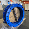
Tilting Check Valves: An Essential Component for Backflow Prevention
In applications such as water treatment, industrial facilities, municipal networks, and power plants, check valves play a vital role in preventing reverse flow. Among various types, the Tilting Check Valve stands out with its superior hydraulic performance and reliable slow-closing mechanism, making it a trusted solution for large pumping stations and long-distance transmission lines.
How It Works
1.Forward Flow – Valve Opens
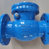
When fluid (such as water, oil, or gas) flows into the valve, the pressure causes the disc to rotate around a tilted shaft, lifting it and allowing the medium to pass through with minimal resistance. The optimized disc angle helps reduce energy loss and ensures smooth operation.
2. Reverse Flow – Valve Closes
When the pressure drops or flow reverses, the disc automatically returns to the closed position, assisted by gravity or reverse pressure. A built-in slow-closing device, such as a hydraulic damper or counterweight, helps delay the closing action, effectively reducing the risk of water hammer and protecting the pipeline system.
Video source: Sierra
What Makes Tilting Check Valves Unique
- Compact butterfly-style body for shorter installation length and lighter weight
- Tilting, double-offset disc allows stable, efficient movement during opening and closing
- Multiple sealing options, including wear-resistant rubber and full-metal seals
- Independent slow-closing mechanism (hydraulic or weighted), designed to operate smoothly and reliably without contact with the fluid
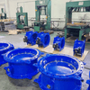
- Adjustable sealing force: A counterweight arm with calibration holes allows fine-tuning of the disc pressure against the seat, ensuring tight sealing even under low backpressure conditions
The Difference Between a Tilting Check Valve and a Regular Check Valve
|
Feature |
Traditional Swing Check Valve |
Tilting Check Valve (Slow-Closing) |
|
Disc Movement |
Vertical swing |
Tilting motion on an inclined axis |
|
Flow Resistance |
Relatively higher |
Lower due to streamlined disc movement |
|
Slow-Closing Function |
Not available |
Integrated mechanism to prevent water hammer |
|
Installation Size |
Typically larger |
More compact and space-efficient |
|
Application Scope |
Standard flow conditions |
High-velocity flow, large-diameter systems |
Union valve Tilting Check Valve specification
|
Parameter |
Description |
|
Model |
Hydraulic Slow Closing Tilting Check Valve |
|
Pressure Rating & Size |
PN10/PN16; DN200~DN1600 (8″~64″) |
|
Material |
Body: GGG40, GGG50, WCB, SS304, SS316 |
|
Structure |
Tilting disc design with lever counterweight slow-closing mechanism (optional hydraulic damper) |
|
Flange Connection |
EN1092-2 standard flange (PN10/PN16) |
|
Applicable Media |
Water, sewage |
|
Temperature Range |
10~80°C |

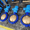
Installation Guidelines for Tilting Check Valves
Proper installation is essential to ensure the reliable performance and longevity of a tilting check valve. Below are the recommended practices and checks for safe and effective installation.
1.Storage Requirements
For soft-sealing valves, keep the sealing surfaces (disc and seat) covered to prevent contamination from dust or debris, which may affect sealing performance.
The valve and any attached slow-closing device (e.g. hydraulic cylinder or counterweight) should be stored in a horizontal position for safety and stability.
2. Pre-Installation Inspection
Before installation, perform the following checks:
- Ensure the valve has not been damaged during transport or storage.
- Verify that the sealing surfaces and valve cavity are clean and free of debris.
- Check that external control piping, if applicable, is intact.
- Confirm that the disc moves freely without obstruction.
- Test that the slow-closing mechanism and limit arm function smoothly and are not jammed.
3. Installation Instructions
A. Orientation and Placement
- Flow Direction: Always install the valve according to the flow direction arrow marked on the valve body. Installing it in reverse may cause the valve to malfunction.
- Recommended Position: Install on horizontal or slightly inclined piping, ensuring the disc can open and close freely.
- Vertical Installation: Only permitted if the valve is specifically designed for it, and the media must flow upwards.
- Suggested Location: Place the valve near the pump outlet to minimize backflow distance and allow quicker closing action.
B. Installation Steps
- Install a suitable gasket between flanges to ensure a tight seal.
- Tighten the flange bolts in a crisscross pattern to ensure even pressure and prevent valve body deformation.
- If the valve includes a hydraulic damper or counterweight, make sure it has adequate space to operate without obstruction.
- For models with a bypass line, ensure all connections are correct and secure.
4. Post-Installation Commissioning
- Test disc movement by manually pushing the counterweight or allowing fluid to flow through and observing valve action.
- For hydraulic models, adjust the throttle valve on the damper to control the closing speed.
- Before initiating full flow, gradually open the upstream valve and observe whether the check valve opens and closes correctly.
Common Issues and Troubleshooting for Tilting Check Valves
|
Issue |
Possible Cause |
Recommended Solution |
|
Leakage at sealing surfaces |
1. Dirt or debris on sealing surface |
1. Clean the sealing area thoroughly |
|
Valve disc is stuck |
1. Shaft connection is worn |
1. Shut off flow and repair or replace worn parts |
|
Slow-closing mechanism jammed |
1. Worn limit arm |
1. Repair or replace |
|
Abnormal noise during operation |
1. Loose valve connections |
1. Retighten all flange bolts |
Final Note
In fluid control systems, performance, reliability, and durability are non-negotiable—and the tilting check valve stands out as an advanced yet practical solution. With an optimized flow path, automatic slow-closing design, and strong adaptability to demanding water conditions, it has become a preferred choice among engineers and system designers.
At Union Valve, we don’t just manufacture valves—we deliver complete solutions. Backed by decades of experience, internationally recognized certifications, and a commitment to quality, our products are trusted in over 100 countries. Whether you need a standard model or a fully customized configuration, our team is here to support your project from design to commissioning.